Overview
It uses a modified Marching Cubes algorithm to generate meshes from an underlying Signed Distance Field comprised of several layers of noise and shape functions. The inspiration for this project was the game Deep Rock Galactic, which boasts one of the best cave generators in gaming. I was inspired to attempt a similar sort of cave generator to learn more about computer graphics and multi-threading.
The source code for this project can be found here, though please note this project is unfinished and still contains several loose ends.
Sections
Isosurface Meshing
What follows is a brief explanation of Marching Cubes so the later sections make sense, so if you already know how it works just skip forward :)
Meshing an isosurface with the Marching Cubes algorithm is dead simple. The isosurface is a three dimentional grid of discrete points, each with some value representing the distance from the terrain surface at that point - this value will be refered to as density. The point grid can be treated as cells, or voxels, each consisting of 8 points each. These cells are given to the marching cubes algorithm and it processes each independently, in sequence or in parallel. First, the marching cubes algorithm evalues the density value at each cell corner to see if it greater or less than zero. Density values greater than zero will be inside the mesh, density values less than zero are outsite and exactly zero is on the surface. The combination of the resulting boolean values result in a unique 'case code' for each cell, up to 256. This case code is fed into an enormous 'triangulation' table, which tells the mesher which edges it needs to connect into triangles to correctly mesh the surface.
int3[] cornerOffsets =
{
    (0, 0, 0), // 0       6--------7
    (1, 0, 0), // 1      /|       /|
    (0, 1, 0), // 2     / |      / |
    (1, 1, 0), // 3    4--------5  |
    (0, 0, 1), // 4    |  2-----|--3
    (1, 0, 1), // 5    | /      | /
    (0, 1, 1), // 6    |/       |/
    (1, 1, 1)  // 7    0--------1
};

byte caseCode = 0;
for (uint i = 0; i < 8; i++)
{
    int3 coordinate = cellIndex + cornerOffsets[i];
    if (SampleDensity(coordinate) > 0)
        caseCode |= (1 << i);
}
With this basic marching cubes implementation, I could generate shapes by implementing the SampleDensity() function as something like:
d = length(coordinate) - radius;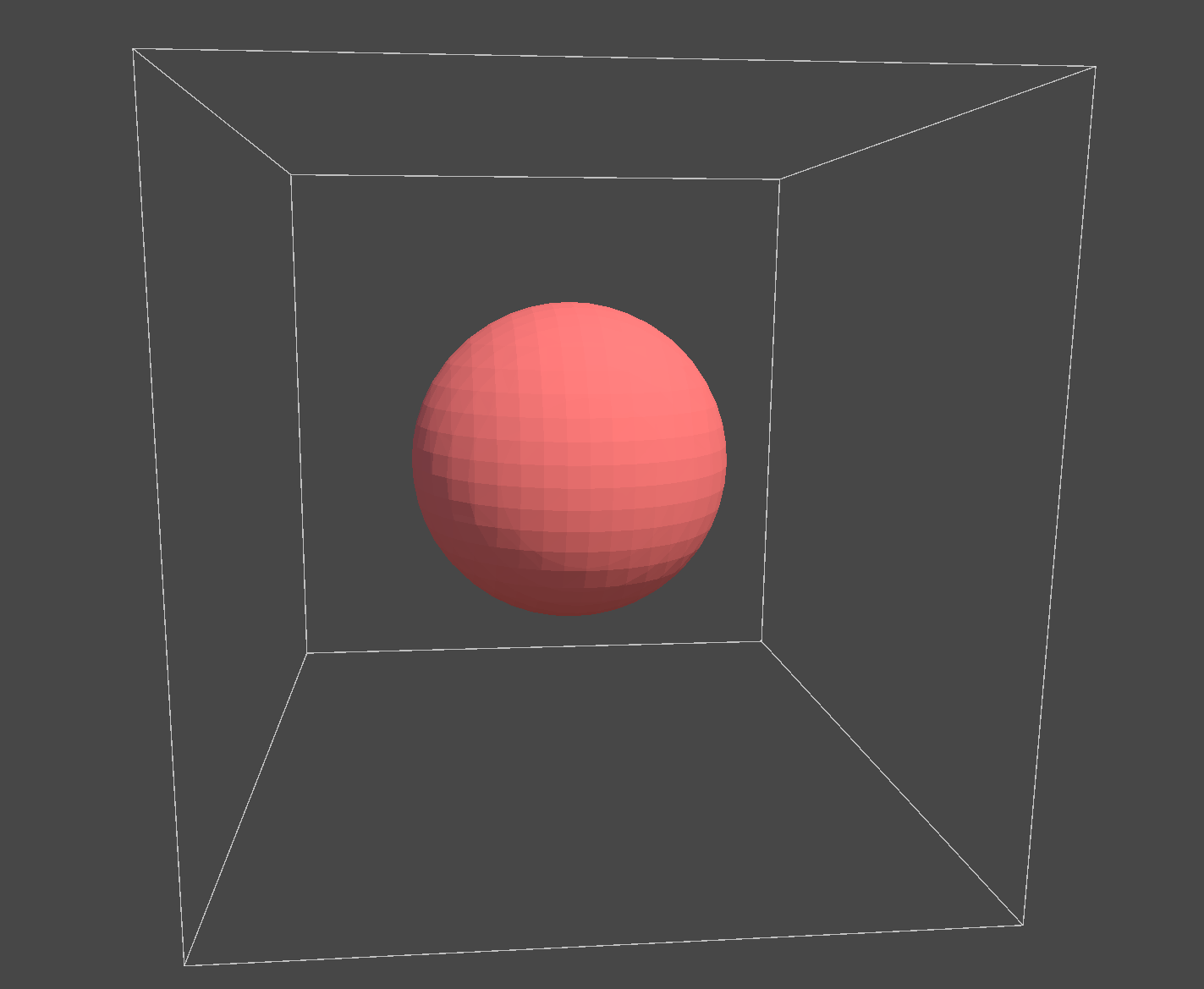
Signed Distance Functions
I mentioned above that the 'density' value used by the Marching Cubes algorithm represents the distance from that point to the nearest surface. Fields with this property are known as Signed Distance Fields and are generally generated by combining Signed Distance Functions (SDFs), mathematical formulas representing shapes. The function above is the SDF for a sphere, which I found on Inigo Quilez's website here, the de facto SDF bible.
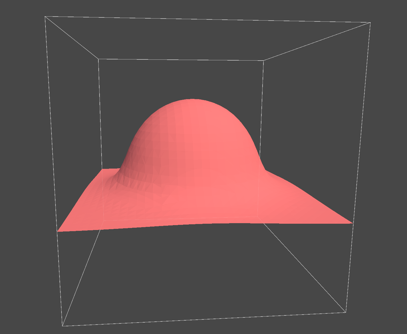
Following this artical on NVIDIA gems, I created a plane with this simple function:
d = -coordinate.y;// Cubic polynomial smin
float SmoothMin(float a, float b, float k)
{
k *= 6.0f;
float h = max(k - abs(a - b), 0.0f ) / k;
return min(a, b) - h * h * h * k * (1.0f / 6.0f);
}
JOBS & Compute Shaders
This was for two main reasons:
- The GPU does not support dynamic memory allocation, meaning it must all be reserved on initialization. - Doing all the processing on the CPU avoids the need for large GPU readbacks for collision data.
I ended up converting my Marching Cubes and SDF algorithms into JOBS, and optimized them to the best of my ability. One interseting optimization was to use SIMD and branchless execution where possible, this article was a big help with that.
Chunking
Each brick can then be handled one-by-one in the main thread. First, each brick goes through a long process of culling:
- First, I evaluate the world-space brick bounding box against the view frustum. Out of view bricks are skipped entirely.
- Next, before queueing the density evaluation, a point at the centre of the brick is evaluated for distance. Because any point in a distance field tells you how close it is to the nearest surface, if the distance at this point is greater than the length from the centre of the brick to one of it's corners, the surface is guaranteed to not intersect this brick and it can be safely skipped.
- Finally within the density evaluator, I keep track of the larges and smallest distance values. If they are both negative or both positive, that brick does not intersect the surface and will not be meshed.
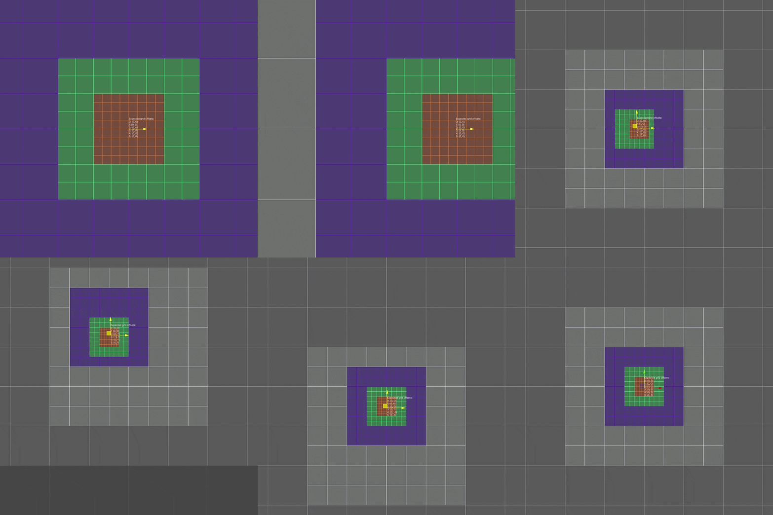
To manage LODs, I used an approach similar to this article on Geometry Clipmaps, see here called brickmaps. As the article suggests, I use a nested grid structure, with each level being double the size of the last while retaining the same number of points. This results in density being calculated at a coarser resolution as you get further from the view origin. However rather than breaking the grids into "footprint pieces", the pieces remain separated into chunks and the level origins are shifted in a way that prevents partial intersections. This means that a single chunk is stable once computed, and can be reused statically until it moves into another brickmap level.
To find the origin of any given brickmap level, I take the observer position and find the coresponding grid index using the next highest brickmap level. This ensures that bricks never partially intersect with one another. Here is the code for the test gif below.
 // Calculate size of one chunk.
float3 chunkSize = k_ChunkSize * math.pow(2, clipmapLevelIndex);
chunkSize.z = 0; // Make 2D for demo.

// Compute the centre chunk index at this clipmap level scale from which to build the remaining chunks.

/* To explain the maths here, to find the position on our grid level we would do:
    *
    * float3 halfChunkSize = chunkSize / 2.0f;
    * float3 scaledOriginPosition = ((float3)transform.position + halfChunkSize) / math.pow(2, level);
    *
    * However, this creates overlaps with higher grid levels, so we calculate it's position on the upper
    * grid level and then multiply it by 2 in the next line to restore it to the correct grid level.
*/

float3 scaledOriginPosition = ((float3)transform.position + chunkSize) / math.pow(2, clipmapLevelIndex + 1);
int3 originChunkIndex = (int3)math.floor(scaledOriginPosition / k_ChunkSize) * 2;/*
* This section sets up the skipping of large chunks rendering over small chunks.
*
* In this 2D example, there are 9 positions a lower grid can be in relation to it's encompassing grid.
* From each case, we must algorithmically decide which chunks to skip in the encompassing grid.
*
* These cases can be represented by an public offset in each axis, with potential values -1, 0 and 1.
* This covers all 9 public position cases.
*
* We can then use each axis in relation with our offset index to skip the proper chunks.
*/
m_ClipmapLevelOrigins[clipmapLevelIndex] = originChunkIndex;
int3 lowerGridOffset = 0;
if (clipmapLevelIndex > 0)
{
lowerGridOffset = m_ClipmapLevelOrigins[clipmapLevelIndex - 1] - originChunkIndex - originChunkIndex;
lowerGridOffset /= 2;
}
Transvoxel
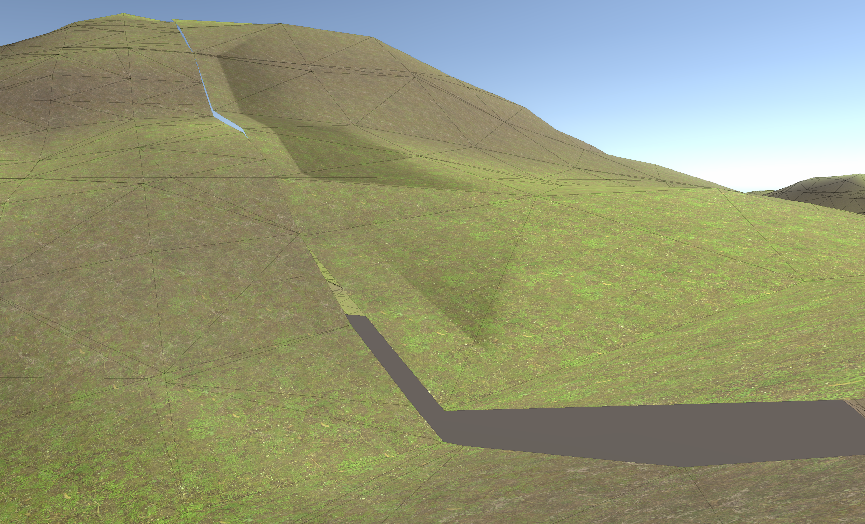
I realized that with a brickmap, only one edge of a brick could be on the border between LODs at a time. This meant I could simply store one transition mesh per brick and change the side if necessary.
Sources
Coding Adventure: Marching Cubes
https://www.youtube.com/watch?v=M3iI2l0ltbEMarching Cubes optimizations in Unity
https://eetumaenpaa.fi/blog/marching-cubes-optimizations-in-unity/#voxelcorners-vs-stackallocGPU Gems 3 - Generating Complex Procedural Terrains Using the GPU
https://developer.nvidia.com/gpugems/gpugems3/part-i-geometry/chapter-1-generating-complex-procedural-terrains-using-gpuInigo Quilez
https://iquilezles.org/GPU Gems 2 - Terrain Rendering Using GPU-Based Geometry Clipmaps
https://developer.nvidia.com/gpugems/gpugems2/part-i-geometric-complexity/chapter-2-terrain-rendering-using-gpu-based-geometryTransvoxel.org
https://transvoxel.org/